Reverse Engineering for Beginners : Floating-point unit(Part2)

1.25.7 Comparison example
Let's try this:
Even though the function is simple, understanding it at the Assembly level will be a bit difficult.
x86
Non-optimizing MSVC
MSVC 2010 produces the following:
Listing 1.214: Non-optimizing MSVC 2010
FLD loads _b into ST(0).
FCOMP compares the value in ST(0) with the value of _a and sets the C3/C2/C0 bits in the FPU status word register. This is a 16-bit register that reflects the current state of the FPU. Also, FCOMP after the comparison pops the value from the stack. And that is the difference between it and FCOM which only compares without popping.
And I will explain to you simply why things are a bit complicated here. Processors before Intel P6 had no jump instructions that could test C3/C2/C0 directly, because back then the FPU was a separate chip.
Modern processors now have:
And these instructions modify the CPU flags directly (ZF / PF / CF).
FNSTSW copies the FPU status word into register AX. The C3/C2/C0 bits are placed at positions: 14 / 10 / 8 — meaning they all reside in the high part of AX which is AH. And so we understand AH, because AH takes bits 8 to 15, and AX is 16-bit, so they are all confined to the AH side.
This is how the C3/C2/C0 bits are positioned in the AX register.

This is how the C3/C2/C0 bits are positioned in the AH register.

After executing the instruction:
Only the two bits C0 and C2 (at positions 0 and 2) are taken into consideration, and all other bits are ignored.
Now let's talk about the parity flag, which is another notable historical artifact.
The parity flag is set to 1 if the number of 1s in the result of the last arithmetic operation was even, and set to 0 if it was odd.
And the author at that point went and checked Wikipedia:
A common reason to test the parity flag is actually unrelated to parity itself. The FPU has four condition flags (C0 through C3), but they cannot be tested directly and must first be copied to the flags register. When this happens, C0 is placed in the carry flag, C2 in the parity flag, and C3 in the zero flag. The C2 flag is set for example when incomparable floating point values (such as NaN or unsupported format) are compared using FUCOM instructions.
As stated in Wikipedia, the parity flag is sometimes used in FPU code. Let's see how.
The PF flag is set to 1 if C0 and C2 are both 0 or both 1, and in that case the instruction JP (jump if PF==1) will execute.
If we recall the C3/C2/C0 values for the different cases, we can see that the conditional jump JP will execute in two cases:
* if b > a
* or if a = b
(Because the C3 bit is not taken into consideration here, as it was zeroed out by test ah, 5).
After that the matter is simple. If the conditional jump happened, the FLD instruction will load the value of _b into ST(0). And if the jump did not happen, the value of _a is what will be loaded there.
What about checking C2?
The C2 flag is set in case of an error (such as NaN, etc.), but our code does not check it. If the programmer cares about FPU errors, additional checks must be added.
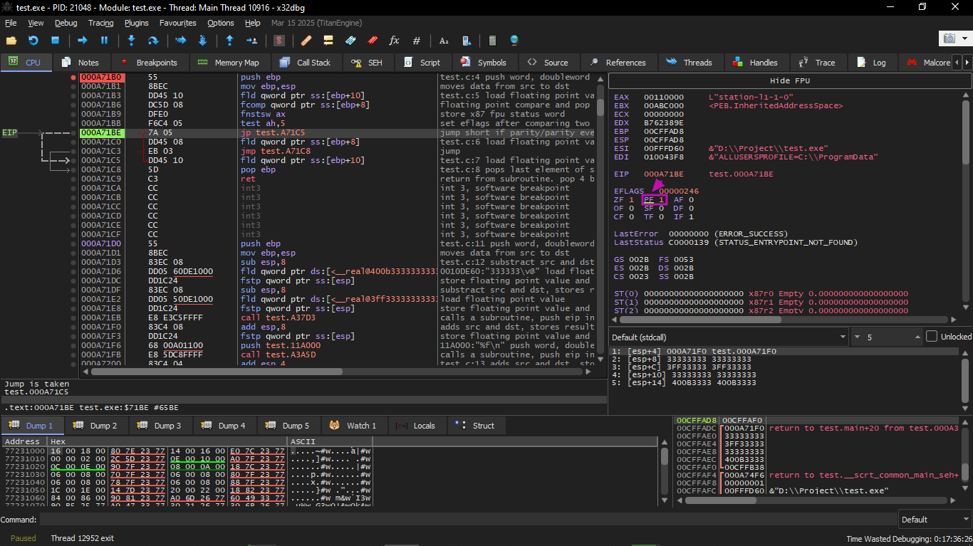
First OllyDbg example: a=1.2 and b=3.4
We will start by compiling the C code using this command:
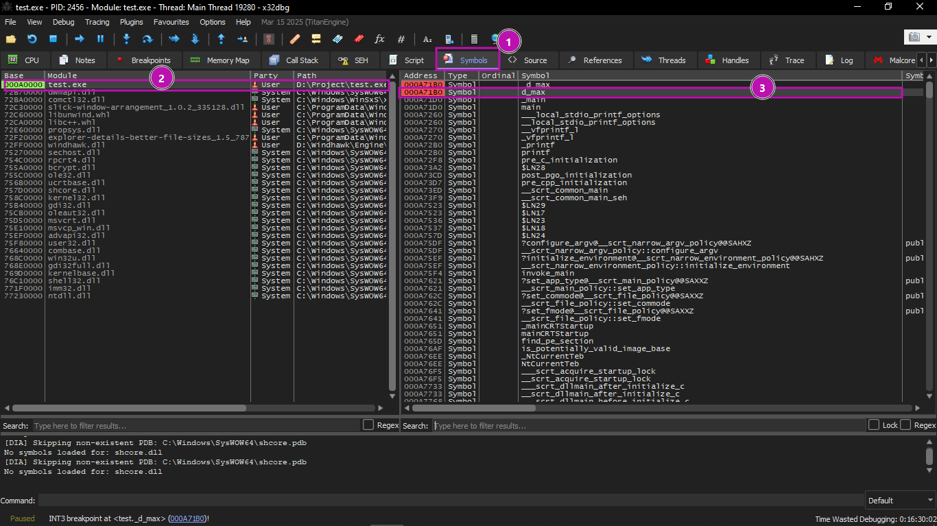
Then we will run the exe on x32dbg, go to symbols, and select the function named d_max.
We will set a breakpoint at the beginning of the function, press F9 until we reach it, and then start stepping with F8.
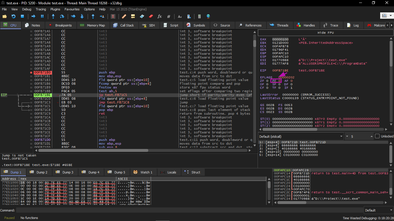
We will start executing the first FLD:
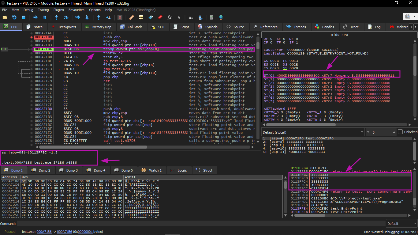
The current function arguments are: a = 1.2 and b = 3.4 (we can see them in the stack: two pairs of 32-bit values). The value b (3.4) is already loaded in ST(0). Now FCOMP is about to execute. x32dbg displays the second operand of FCOMP, which is currently on the stack.
FCOMP was executed:
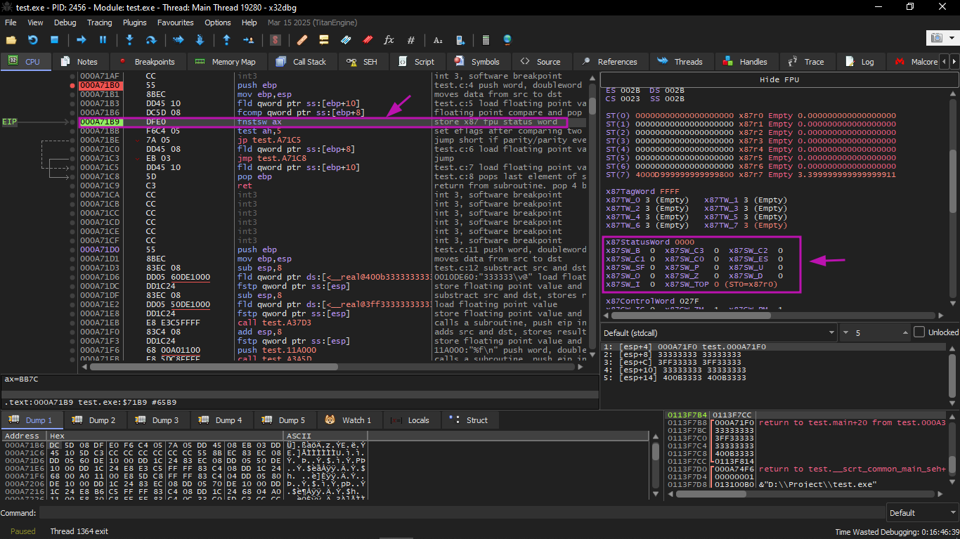
We see the state of the FPU condition flags: all zeros.
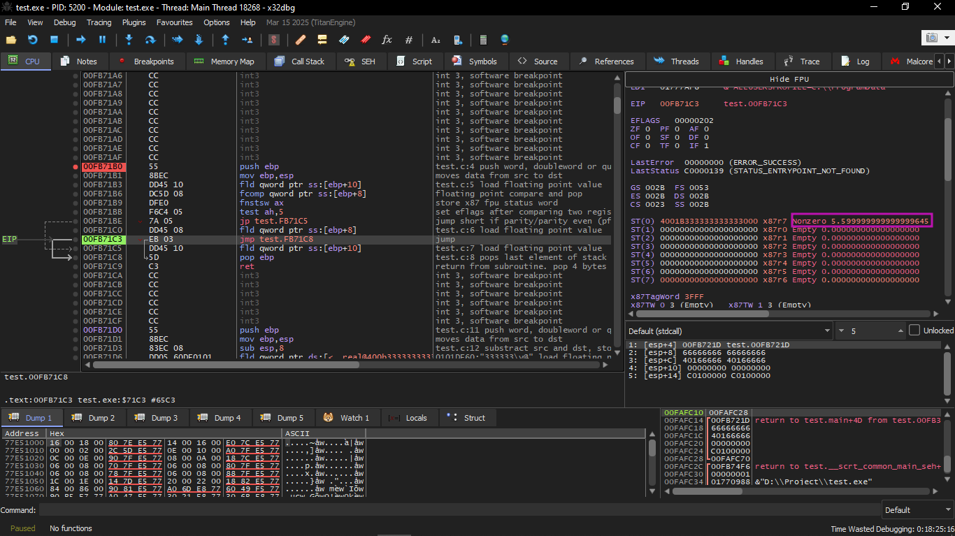
FNSTSW was executed:
We see that register AX contains zeros: indeed all condition flags are zero. (OllyDbg decodes FNSTSW as FSTSW — they are synonyms).
TEST was executed:
The PF flag is set to 1. Indeed: the number of set bits in 0 is 0, and 0 is an even number. x32dbg decodes JP as JPE — they are synonyms. And it is about to execute now.
JPE executed, and FLD loaded the value b (3.4) into ST(0).
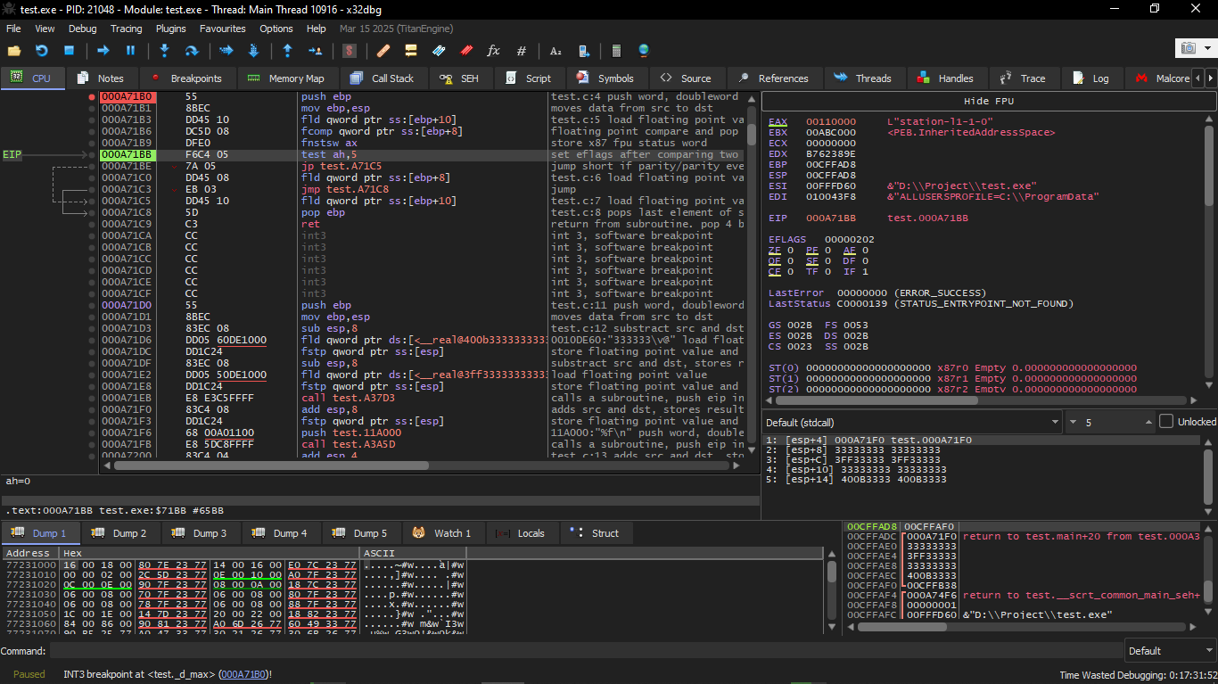
Second OllyDbg example: a=5.6 and b=-4
Let's do a second example:
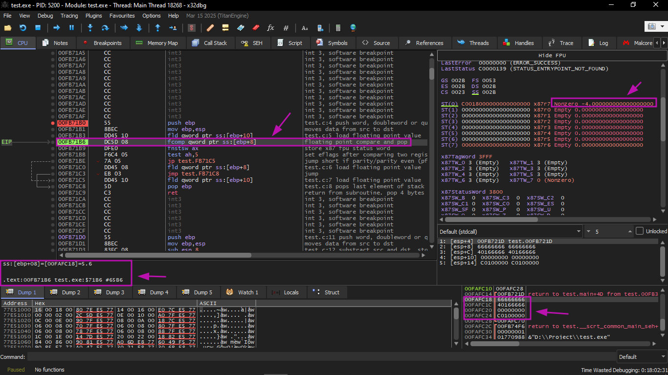
The current function arguments are: a = 5.6 and b = −4. The value b (−4) is already loaded in ST(0). FCOMP is about to execute now. x32dbg displays the second operand of FCOMP, which is currently on the stack.
Then we will execute FCOMP:
We see the state of the FPU condition flags: all zeros except C0.
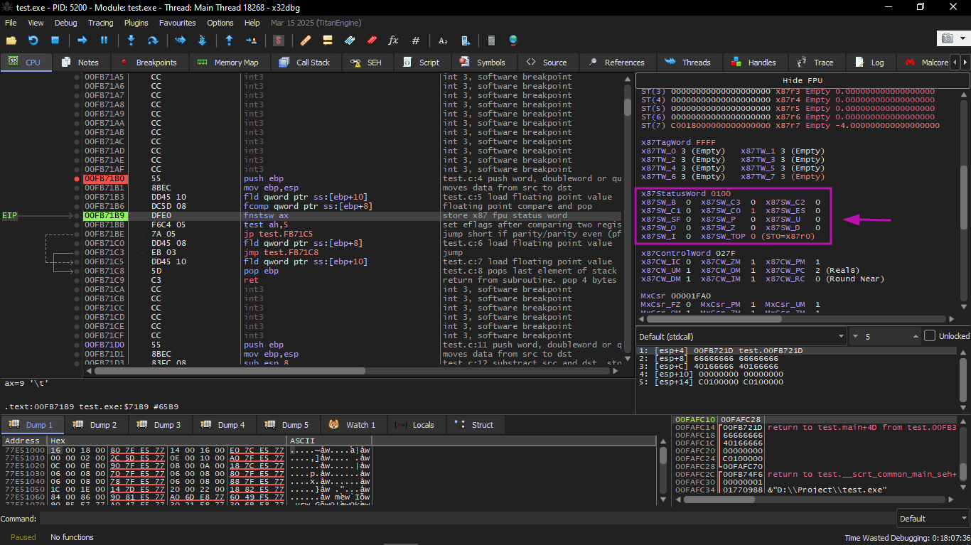
Then FNSTSW will execute:
We see that register AX contains 0x100: the C0 flag is present in bit number 8.
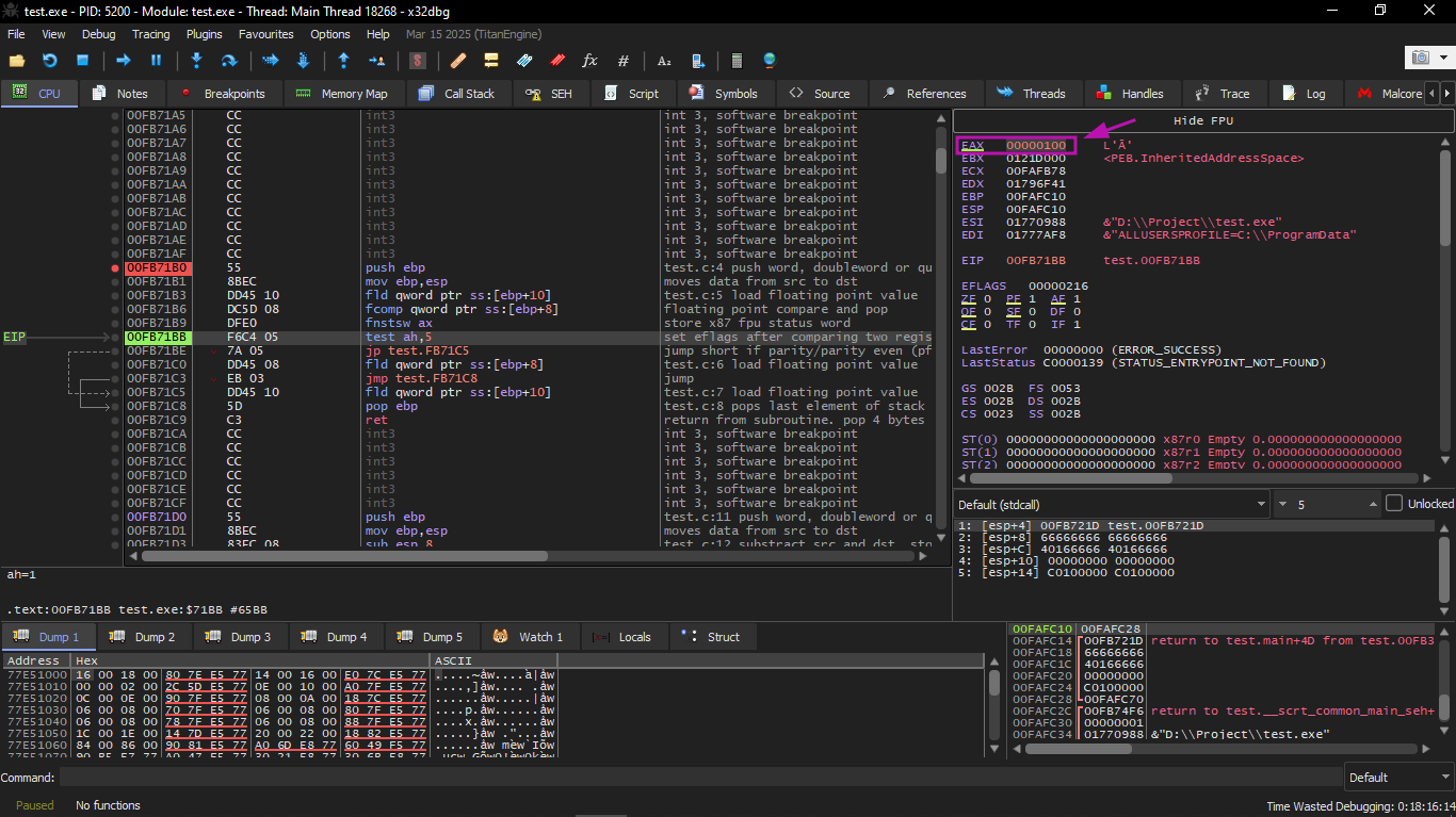
Then we will execute JP:
Here you will find that the PF flag is zeroed. Indeed: the number of set bits in 0x100 is 1, and 1 is an odd number.
JPE is now skipped (does not execute). And since JPE did not execute, FLD loaded the value a (5.6) into ST(0):
After that the function finishes.
Optimizing MSVC 2010
The FCOM instruction differs from FCOMP in that it only compares the values without modifying the FPU stack.
Unlike the previous example, here the operands are coming in reverse order, and therefore the comparison result in the C3/C2/C0 bits is different:
* if a > b in our example, then C3/C2/C0 bits will be: 0, 0, 0
* if b > a, then the bits will be: 0, 0, 1
* if a = b, then the bits will be: 1, 0, 0
The instruction:
Leaves only two bits — C3 and C0. Both will be zero if a > b, and in that case the JNE jump will not execute.
After that comes:
This instruction copies the value in ST(0) to the operand, and also pops a value from the FPU stack. In other words: it copies ST(0) (which currently holds _a) and places it into ST(1). After that there will be two copies of _a at the top of the stack. Then one value is popped. In the end ST(0) contains _a, and the function finishes.
The conditional jump JNE executes in two cases:
* if b > a
* or if a = b
In that case:
This will copy ST(0) into ST(0) itself (meaning it did nothing — like a NOP), and then one value is popped from the stack, so the top value in the stack (ST(0)) will become the value that was previously in ST(1) (which is _b). After that the function finishes.
The reason this instruction is used here is likely that the FPU has no other instruction that pops a value from the stack and discards it without copying it first.
GCC 4.4.1
Listing 1.216: GCC 4.4.1
The FUCOMPP instruction is roughly like FCOM, but it pops both values from the stack and handles not-a-numbers differently.
A few words about not-a-numbers.
The FPU can deal with special values called not-a-numbers or NaNs. These are things like infinity, the result of division by zero, etc. Not-a-numbers can be either quiet or signaling.
It is possible to continue working with quiet NaNs, but if anyone tries to perform any operation with signaling NaNs, an exception occurs.
The FCOM instruction raises an exception if any operand is a NaN. But FUCOM only raises an exception if any operand is a signaling NaN (SNaN).
The next instruction is SAHF (Store AH into Flags) — and this is a rare instruction in code that is not related to the FPU. 8 bits from AH are transferred to the first 8 bits of the CPU flags in the following order:
Let's recall that FNSTSW transfers the bits that matter to us (C3 / C2 / C0) into AH:

And they are located at positions 6, 2, and 0 in register AH.
In other words, the pair of instructions:
Transfer C3 / C2 / C0 into ZF, PF, CF.
Now let's recall the C3 / C2 / C0 values in the different cases:
If a > b in our example:
If a < b:
If a = b:
In other words, these CPU flag states are possible after the instructions:
Based on the flag state and the conditions, the SETNBE instruction places 1 or 0 into AL. It is roughly the opposite of the JNBE instruction, but the difference is that SETcc places 1 or 0 into AL, while Jcc either jumps or does not.
SETNBE places 1 only if:
If this condition is not met, 0 is placed into AL.
The only case where both CF and ZF are 0 is when:
In that case 1 is stored in AL, the JZ instruction that follows will not execute, and the function will return a. In all other cases, b is what will be returned.
Optimizing GCC 4.4.1
Listing 1.217: Optimizing GCC 4.4.1
It is roughly the same thing, the only difference is that the JA instruction was used after SAHF. In fact, the conditional jump instructions that check for "greater", "less", or "equal" in unsigned number comparisons (such as these instructions):
Only check the flags:
Let's recall where the C3 / C2 / C0 bits are located in register AH after executing FSTSW / FNSTSW:

Let's also recall how the bits from AH are stored into CPU flags after executing SAHF:

After the comparison, the C3 and C0 bits are transferred into:
So that the conditional jump instructions can work after that. The JA instruction executes if CF = 0 and ZF = 0.
And thus, the conditional jump instructions mentioned above can work after the pair of instructions:
It is clear that the FPU condition bits C3 / C2 / C0 were placed in those positions intentionally, so that they can be easily converted to regular CPU flags without needing additional operations to rearrange the bits.
GCC 4.8.1 with -O3 optimization
Some new FPU instructions were added in the Intel P6 family. These are FUCOMI (compares operands and sets the main CPU flags) and FCMOVcc (works like CMOVcc, but on FPU registers).
It is clear that the GCC developers decided to drop support for Intel processors older than P6 (old Pentiums, 80486, etc.). Also, the FPU is no longer a separate unit in the Intel P6 family, so it is now possible to modify or check the main CPU flags through the FPU.
So what we get is the following:
Listing 1.218: Optimizing GCC 4.8.1
It is hard to guess why FXCH is present here. We could easily get rid of it by swapping the first two FLD instructions, or by replacing FCMOVBE (below or equal) with FCMOVA (above). This may be imprecision from the compiler.
FUCOMI compares ST(0) (a) and ST(1) (b) and then sets some flags in the main CPU.
FCMOVBE checks the flags and copies ST(1) (which is b here) into ST(0) (which is a here) if ST(0)(a) <= ST(1)(b). Otherwise (a > b) it leaves a in ST(0).
The last FSTP instruction leaves ST(0) at the top of the stack and discards the content of ST(1).
Let's trace this function in GDB:
As mentioned before, the FPU register set is a circular buffer not a real stack. GDB does not display STx registers, but instead displays the internal FPU registers (Rx).
The arrow points to the current top of the stack. We can also see the value of the TOP register in the Status Word — it is 7 now, meaning the top of the stack currently points to internal register number 7.
The values of a and b were swapped after executing FXCH. The FUCOMI instruction was executed — we can see that CF is set. The FCMOVBE copied the value of b. The FSTP left one value at the top of the stack. The TOP value is now 7, so the top of the FPU stack points to internal register 7.
ARM
Optimizing Xcode 4.6.3 (LLVM) (ARM mode)
Listing 1.220: Optimizing Xcode 4.6.3 (LLVM) (ARM mode)
Very simple. The incoming values are placed in registers D17 and D16 and then compared with VCMPE.
Just like the x86 coprocessor, the ARM coprocessor has its own status register and flags (FPSCR), because it needs to keep condition flags specific to the coprocessor. And just like x86, there are no conditional jump instructions in ARM that can directly check the coprocessor flags. That is why there is the VMRS instruction that transfers 4 bits (N, Z, C, V) from the coprocessor status register to the general purpose register (APSR).
VMOVGT is like MOVGT but for D registers, and it executes only if the first value is greater than the second (GT = Greater Than). If it executes, the value of a will be copied into D16 (which originally held b). If not, b remains in D16.
The second-to-last instruction (VMOV) prepares the value in D16 to be returned via the R0:R1 pair.
Optimizing Xcode 4.6.3 (LLVM) (Thumb-2 mode)
Listing 1.221: Optimizing Xcode 4.6.3 (LLVM) (Thumb-2 mode)
Almost the same as before, but with a small difference. As we know, in ARM mode many instructions can have a predicate added to them. But in regular Thumb mode there is no space for that at all because instructions are 16-bit. However, Thumb-2 was extended to allow adding these conditions to some older instructions. In the listing produced by IDA, we see VMOVGT like before. In reality it is a regular VMOV, but IDA added the -GT suffix because there is an IT GT instruction immediately before it.
The IT instruction defines an "if-then" block. After it you can place up to 4 instructions, each with a condition suffix. In this example, IT GT means the instruction that follows will execute only if the GT condition is true.
A more complex example, from Angry Birds (iOS):
Listing 1.222: Angry Birds Classic
ITE means if-then-else, and assigns suffixes to the next two instructions. The first executes if the condition (NE = Not Equal) is true, and the second executes if the condition is not true (the inverse of NE is EQ). The instruction after VMOVEQ is a normal instruction with no suffix (BLX).
Another slightly more complex example, also from Angry Birds:
Listing 1.223: Angry Birds Classic
If it were for example ITEEE EQ, the suffixes would be: EQ, NE, NE, NE.
Another example from Angry Birds:
Listing 1.224: Angry Birds Classic
ITTE (if-then-then-else) means the first and second instructions execute if LE is true, and the third executes if the inverse condition (GT) is true.
Compilers generally do not use all combinations. In Angry Birds (Classic version) only the following were used: IT, ITE, ITT, ITTE, ITTT, ITTTT.
Non-optimizing Xcode 4.6.3 (LLVM) (ARM mode)
Almost the same idea, but there is a lot of extra code because a and b were sent to the local stack, and even the value to be returned is also on the stack.
Optimizing Keil 6/2013 (Thumb mode)
Keil does not generate FPU instructions directly because it is not guaranteed that the target CPU has an FPU at all, and it cannot do a normal bitwise comparison. So it calls the external function __aeabi_cdrcmple to perform the comparison and leave the result in the flags, after which BCS (Carry Set = Greater or Equal) acts on it directly.
ARM64
Optimizing GCC (Linaro) 4.9
In ARM64 there are now FPU instructions that set the flags in APSR directly instead of FPSCR, which is much more convenient.
FCMPE compares the two values in D0 and D1 and sets the flags in APSR. FCSEL (Floating Conditional Select) copies D0 or D1 into D0 based on the GT condition, and also uses APSR flags. Much more convenient than the old way.
If the GT condition is true → D0 remains as it is (a). If not true → D1 (b) is copied into D0.
Non-optimizing GCC (Linaro) 4.9
The non-optimizing version is much more verbose and repetitive. It saves the inputs to the stack (Register Save Area), reloads them, converts them back to D-registers for comparison, then uses an old-style conditional branch (BLE) instead of the clean FCSEL.
Optimizing GCC (Linaro) 4.9 — float
If we change the function to use float instead of double:
The code produced is:
Exactly the same idea, but using S-registers (32-bit) instead of D-registers (64-bit), because float is passed in S0 and S1.
MIPS
The coprocessor in MIPS has a condition bit that can be set in the FPU and read in the CPU. The old MIPS had only one bit (FCC0), the new one has 8 (FCC0 through FCC7), and these are in a register called FCCR.
Listing 1.227: Optimizing GCC 4.4.5 (IDA)
c.lt.d compares Less Than for double. If b < a the condition bit is set (True). bc1t branches if Condition 1 is True (if the bit is set, jump). The delay slot is very important in MIPS — the instruction after the branch always executes.
1.25.8 Some constants
It is easy to find the representation of some constant numbers in IEEE 754 on Wikipedia. For example, 0.0 is represented by 32 zeros (float) or 64 zeros (double). This means that to zero a floating point variable in a register or in memory, it is possible to use MOV or XOR reg, reg. This is very useful in structures (structs) that contain many types, because with a single memset you can zero all integers to 0, booleans to false, pointers to NULL, and floats to 0.0.
1.25.9 Copying
One might think that FLD/FST must be used to copy IEEE 754 numbers, but in reality a regular MOV copies them bitwise just like any other data, and that is simpler and faster.
1.25.10 Stack, calculators and reverse Polish notation
Now we understand why old programmable calculators used Reverse Polish Notation (RPN). For example, to add 12 + 34, you enter 12, then 34, then press +. Because those calculators were stack machines, and that was much easier than dealing with parentheses and complex expressions. They are still present in many Unix distributions to this day: the program dc.
1.25.11 80 bits
The internal representation in the x86 FPU was 80-bit. A somewhat odd number since it is not a power of 2. There is a theory that this is due to historical reasons — the IBM card used in punching cards encoded 12 rows × 80 columns. Also the 80×25 text mode resolution was widespread back in those days.